
How do you connect wires to a PCB?
This article intends to illuminate various approaches to connect wires to a Printed Circuit Board (PCB), providing detailed insights into different soldering methods, connectors, and alternative techniques. We will explore the benefits of PCB wiring, examine alternative attachment methods, and dissect more cost-effective options for wire joining.
Methods of Connecting Wires to a PCB
Each of these components plays a crucial role in bringing electronic devices to life. Without wires, a PCB is sent into an indefinite intermission. But how exactly do these wires connect to PCBs and ensure technological performances go as planned?
Soldering
Soldering is the most frequently utilized method when it comes to attaching wires to a PCB. It is the process of merging two metals using a filler material, usually, a solder wire that melts when heated. This molten solder wire hardens as it cools, forming a delicate yet robust joint between the wire and the PCB. This process ensures a guaranteed electrical connection that withstands the test of time in a tiny footprint on the PCB real estate.
Terminal Blocks
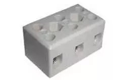
Despite the popularity of soldering, some might find it quite a process, time-intensive, and requiring extra dexterity. Enter the Terminal blocks, an excellent alternative for those who prefer a less complicated, more accessible approach. Terminal blocks are small, modular blocks containing one or more tiny clamps. These clamps are designed to hold and secure wires, ensuring they stay affixed to your PCB. Just insert the wire into the block, tighten the screw, and voila - you have a secure, firm connection.
Crimp Bootlace Ferrules
These cylindrical metal tubes are crimped onto the end of a wire, using a particular crimping tool. The ferrules' intended protective metal casings ensure that the wire strands remain together and don't fray or damage over time. When connected to a PCB, these crimped wires offer an additional layer of security and longevity - a feature particularly useful for configurations involving high voltages or movable components.
In the grand scheme of things, the method you choose to connect wires to your PCB depends primarily on the specific needs of your project.
Note: While these are popular methods to connect wires to a PCB, professional technicians or engineers should ideally handle them due to the risks associated with dealing with electronic components.
Soldering Wires to a PCB
The art of soldering wires to a Printed Circuit Board (PCB) is intricate and detailed. Let's break down the types of solder wires used and compare the methods of manual welding vs machine welding.
Solder Wire Types
One of the most versatile and commonly used solder wires is the lead-tin alloy. This type of alloy brings a balance of functionality and durability, making it aptly suitable for the soldering process. Let's delve into a few key attributes that make lead-tin so universally used:
| Attribute | Function |
| High Versatility | It is capable of being used in multiple environments and across varied industries. |
| Strength | Ensuring the circuit’s longevity. |
| Thermal Fatigue Resistance | Lead-tin alloy offers excellent resistance to thermal fatigue, making it a go-to choice for PCB soldering. |
Manual Welding vs Machine Welding
In the realm of soldering, there are two primary methods of sealing the deal - manual welding and machine welding.
Manual welding is when skilled technicians use a handheld soldering iron to form the connections. This method provides superior flexibility and adaptability, perfect for custom projects or intricate designs.
Machine welding involves automated machines doing the soldering. This makes it exceptionally efficient for large-scale production runs, where consistency and speed are prime factors.
Types of PCB Connectors
One of the key aspects of building a successful electronic circuit system lies in its interconnections, notably via PCB (Printed Circuit Board) connectors. Let's dive into the different types of PCB connectors and their applications in our everyday electronics.
Wire-to-Wire Connectors
Wire-to-wire connectors are a type of tool used in attaching or joining two wires together. In simple terms, they facilitate a seamless flow of electric current from one wire to another. You might recognize these handy little pieces from their use in vehicle systems, home appliances, and even industrial machinery.
- Offer a quick disconnect feature
- Enable reversed connections
- Can withstand strenuous conditions such as heat or vibration
You'll find these indispensable connectors in everything from your household microwave to industrial-grade machinery.
Board-to-Wire Connectors
Board-to-wire connectors offer a direct linkage from a wire to a PCB board. A common example most people would be familiar with is a standard computer USB port.
- Ensures secure and stable electrical connection
- Available in several pin counts to cater to different requirements
- High durability against thermal and mechanical stress
It's worth mentioning that for our laptops, smartphones, and other digital devices, these board-to-wire connectors are doing the heavy lifting behind the scenes.
Board-to-Board Connectors
Board-to-board connectors take center stage when multiple circuit boards are involved, enabling communication and electric current flow between them. These connectors are further classified into various types like pin headers and socket connectors, showcasing their diverse applications in multiple fields.
- Can be customized to accommodate unique physical requirements
- Allow for simpler and faster assembly processes
- Can safely handle considerable electrical loads
Whether it's in your gaming console or digital camera, these connectors are driving the core functionality of countless electronic devices.
Wire-to-Board Connectors
Finally, we have wire-to-board connectors which, as their name suggests, connect wires directly to a PCB. These are vital links in several electronics, from refrigerators to televisions.
- Highly adaptable to various board layouts
- Compact and lightweight
- Simplifies assembly process
In summary, whether it's a wire-to-wire, board-to-wire, board-to-board, or a wire-to-board connector, each type of PCB connector plays a critical role in our daily electronics usage.
Advantages of PCB Wiring
Hailed for their ability to streamline the wiring and assembly process, PCBs boast a multitude of benefits that not only simplify circuit manufacturing but also enhance its functionality.
One major advantage that has driven the widespread adoption of PCBs in the electronics industry lies in their ability to facilitate automated assembly. With PCBs, manufacturers can sidestep the intricate task of manual wiring, making circuit production considerably more rapid and efficient. Electronics companies can mass-produce circuits at a fraction of the time it takes with other wiring methods. Plus, they're saving big bucks on labor costs as well.
Moreover, PCBs deliver incredible precision. The automated assembly process is conducive to eliminating human error, resulting in circuits that perform more reliably and consistently. This, in turn, minimizes the risk of circuit faults, leading to considerable savings in maintenance and repair costs.
But the benefits of PCB wiring don't stop there:
- Compact Size: PCBs are known for their compact and tidy design, which is a boon for modern electronic devices striving for sleeker, more compact designs. Thanks to PCBs, manufacturers can integrate a swarm of complex circuits into tiny spaces.
- Easy Replication: Once a PCB design is finalized, it can be reproduced countless times with identical accuracy. This makes it effortless to mass-produce a certain type of circuit, especially given the increased demand for consistency in electronic devices.
- Reduced Noise: PCBs are designed in such a way that they minimize electronic noise, which can interfere with the performance of devices. By ensuring that components are correctly laid out and that the path lengths between them are minimized, PCBs can enhance performance by ensuring a steady flow of signals without significant loss.
Indeed, the advantages of PCB wiring are clear; they offer efficiency, accuracy, and cost-effectiveness. As such, it's easy to see why they're the preferred choice for most electronics manufacturers.
Alternative Techniques for Attaching Wires to PCBs
Even if you're a seasoned professional or an electronics hobbyist, the process of attaching wires to Printed Circuit Boards (PCBs) can feel intricate. Fortunately, options abound when it comes to attaching wires to PCBs. Let's delve into some of the alternative techniques that offer both efficiency and practicality.
Terminal Blocks
Terminal blocks, also known as connection terminals, serve as popular mechanisms in wire-to-board and wire-to-wire connections.
| Advantage | Description |
| Simple yet Effective | Employing a screw-capture method, these blocks ensure a secure fit for your wires. |
| Versatile | They are compatible with a range of wire sizes, accommodating both narrow and thick wires to meet various requirements. |
| Removable | The ease of disassembly is an additional appealing feature of terminal blocks. Simply loosen the screw, and the disconnection process is completed. |
| Accessible | Terminal blocks are readily available from a variety of sources, including online electronics retailers and local stores, making them easily accessible. |
While terminal blocks are convenient and efficient, keep in mind that their size could be a downside if working with space-constrained PCBs.
Connectors
Connectors comprise another common approach for PCB wire attachments. These are typically categorized into two types: through-hole and surface-mount.
| Connector Type | Description |
| Through-hole Connectors | These require holes in the PCB for attachment. Once soldered into place, they provide a robust connection unlikely to break under normal circumstances. |
| Surface-Mount Connectors | Attached directly to the PCB's surface, these connectors streamline the assembly process. They're notably handy when dealing with high-density PCBs. |
Overall, connectors are praised for facilitating easy wire connections and disconnections. However, they can be more difficult and costly to implement than other means.
Quick Fix Glue
Quick fix glue stands out from conventional attachment methods, providing a solution when traditional techniques fail.
| Advantage | Unlike soldering, using quick-fix glue doesn't require extraordinary skill or specific training. |
| Convenience | This adhesive can be applied anywhere on the PCB, offering a quick fix when you're in a pinch. |
| Security | It aids in holding wires in place, preventing unintentional disconnects during handling. |
| Easy Use | Unlike soldering, using quick fix glue doesn't require extraordinary skill or specific training. |
Despite these merits, one should use quick-fix glue sparingly and as a last resort. Overreliance might lead to untidiness and potential damage to the PCB.
In conclusion, the technique you choose for wire attachment majorly depends on your project's requirements and personal preference. The key is to find a balance between simplicity, effectiveness, and cost.
SMT and Reflow Soldering
Surface Mount Technology, widely known as SMT, is an innovative method used in the creation of electronic circuits where components are mounted directly onto the surface of printed circuit boards (PCBs). The rise in popularity of SMT is attributable to its numerous advantages. These may include but are not limited to:
- Compactness: Due to its efficient design practices, SMT allows for more components per square inch than older methods.
- Performance Under Shock: Since the components in SMT are smaller, they have shorter internal lead lengths, which can lead to enhanced performance under shock and vibration.
- Low Manufacturing Cost: SMT automates the entire chip mounting process, thereby reducing the labor cost, which can significantly bring down the entire manufacturing cost.
While the SMT process is exceptionally beneficial, it would be incomplete without mentioning the indispensable tool used extensively in its procedures – the reflow soldering technique. Reflow soldering is the most common method used in factories for surface mount technology.
Reflow soldering works by first applying solder paste to the printed circuit board. The components are then placed on top, and the whole assembly is heated. As the temperature rises, the solder paste reflows, or "turns liquid." It then cools down and forms a solid bond, effectively attaching components to the PCB.
The beauty of reflow soldering is mainly seen in its process simplicity and practical outcomes:
| Advantage | Description |
| Easy assembly | The assembly of intricate circuit boards can be achieved with efficiency when the correct application of solder paste is ensured. |
| High throughput | This methodology is conducive to the rapid assembly of a multitude of PCBs, making it especially well-suited for high-volume manufacturing. |
| Reliable connections | When executed correctly, the reflow soldering process yields exceptionally dependable electrical connections. |
To sum it up, both Surface Mount Technology and reflow soldering offer significant advantages including compact design, higher performance, cost-effectiveness, easier assembly, high throughput, and reliable connections. These technologies continue to evolve with industry needs, promising advancements for the future of electronics manufacturing.
Inexpensive Wire Joining Methods
Increasingly, more and more people interested in DIY electronic repairs are seeking out inexpensive methods for tasks like wire joining. Now, we will explore three straightforward and cost-effective techniques for connecting wires: wire stripping, solder application, and the utilization of electrical tape.
Stripping the Wires
The first step in achieving a secure and effective wire joint is wire stripping. This process exposes the metal inside the wire's protective coating, allowing for a solid connection. Do this meticulously, as any damage to the wire can affect the quality of your connections.
- Start by using a wire stripper to remove about an inch of insulation from the wire ends.
- Carefully rotate the stripper around the circumference of the wire to avoid cutting the metal strands underneath.
- Then, gently pull off the insulation to reveal the bare wire.
Applying Solder
After the wires have been stripped, it's time to strengthen the joint by applying solder; a thin metal alloy that bonds metal surfaces together when heated.
- Firstly, twist the freshly stripped wires together.
- Next, heat the joint using a soldering iron until it’s hot enough to melt the solder.
- Following that, apply the solder to the joint, let it flow, and cover the twisted wires, creating a solid joint once it cools down.
Using Electrical Tape
Once the solder has cooled and solidified, it's important to offer it some protection from external factors such as moisture and physical damage. It insulates the joint, preventing any short circuits.
- Wrap the electrical tape around the soldered joint, starting from the bottom and working your way up till you have covered the entire joint.
- Make sure the tape is wrapped tightly to prevent any moisture from seeping in.
Conclusion
Understanding the various methods of connecting wires to a PCB is crucial to creating effective and durable electronic circuits. Depending on your project's specifics, soldering, terminal blocks, or connectors may be the most suitable. Moreover, the type of wire and connector, as well as the method you use to join them, can significantly impact the overall quality and performance of your device.
In certain scenarios, alternatives like quick-fix glue, wire crimping, or using terminal blocks such as the reliable ones offered by SHINING E&E INDUSTRIAL CO., LTD can be the optimal choice.