
What is a Solid-state Relay (SSR): How It Works, Uses, and More
2025/11/20 SHINING E&E INDUSTRIAL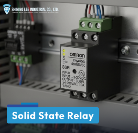
What is a Solid-state Relay (SSR)
Solid-state relays (or solid relays) are widely used in modern electronics and industrial systems as a reliable alternative to traditional mechanical relays. In this article, we’ll cover the basics of how solid-state relays work, general types, their key advantages, and the most common solid-state relay applications. Let’s dive in!
What is a Solid-state Relay?
A solid-state relay (SSR) is an electronic switch that controls electrical loads without any moving parts. Unlike traditional relays (mechanical) using physical contacts to switch power, SSRs rely on semiconductor technology to do the same job. Because they don’t have mechanical contacts that wear out, SSRs are quieter, last longer, and are more reliable.
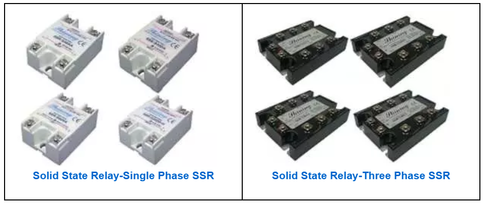
They allow a small input signal, usually as low as 3 volts DC, to control larger loads like motors, heaters, or lighting systems. In short, SSRs make switching faster and more dependable compared to mechanical relays. Here are some examples of SSR from Shining E&E:
Parts of a Solid-state Relay
Although SSRs look simple on the outside, several important parts work together inside:
-
Control Circuit (Input Side): This is where the low-voltage control signal (AC or DC) enters. It prepares the signal to drive the relay.
-
Optocoupler (Photocoupler): This barrier separates the input signal from the output power circuit by providing galvanic isolation to block noise and voltage spikes. It also transfers the electrical signal between the input and output circuits. When activated by the control circuit, an LED on the input side shines across a gap to a light sensor (like a photodiode or phototransistor) on the output side, triggering the output circuit.
-
Output Circuit: This handles the heavy lifting. Using semiconductors such as thyristors, triacs, or MOSFETs, it controls the flow of electricity to the load.
-
Heat Sink: Since semiconductors create heat, many SSRs include a heat sink to prevent overheating.
-
Overvoltage Protection: A built-in safeguard that shuts down the circuit to protect it when the voltage spikes above a safe operating level.
-
Status Indicators: Some SSRs feature small LEDs that show whether the relay is active or not, giving users a quick visual check.
How Does a Solid-state Relay Work?
The working principle of an SSR is simple once you break it down step by step:
1. Receiving and Processing the Control Signal: The operation begins when a low-voltage control signal, often as little as 3V DC, is applied to the input terminals of the SSR. This signal comes from a control source. Instead of directly switching the load, the control signal activates the relay’s internal control circuit. At this stage, an LED inside the optocoupler lights up. This LED acts as the “messenger” that starts the switching process while keeping the input side electrically isolated from the output side.
2. Isolation and Triggering of the Output Circuit: The LED inside the optocoupler shines across a small air gap toward a photosensitive component on the output side. This setup provides complete electrical isolation between the low-voltage input and the high-power output, ensuring safety. When the photosensor detects the light, it triggers the semiconductor switching devices. These devices act as the “electronic switches” that can handle much larger currents and voltages than the original input signal.
3. Switching the Load On and Off: Once the semiconductor devices are triggered, they close the output circuit, allowing current to flow from the power source to the load. This instantly powers the connected device. When the input control signal is turned off, the LED inside the optocoupler also switches off, causing the semiconductor devices to revert to their non-conducting state. This opens the output circuit and disconnects power from the load.
Solid-state vs Mechanical Relay
Before we compare them, let’s first understand what a mechanical relay is. A mechanical relay is an electrical switch that uses an electromagnet and moving contacts to open or close a circuit. When a small control voltage is applied, the electromagnetic coil is energized, pulling the contacts together (or apart) to switch a load on or off. Unlike the SSRs’ switching mechanism, which relies only on semiconductors, mechanical relays combine both electrical and mechanical actions.
Now let’s look at how solid-state relays differ from mechanical relays:
-
Speed: SSRs are much faster, switching in about 1 millisecond or less. Mechanical relays are slower since their contacts need time to move, usually around 10 milliseconds or more.
-
Lifespan: With no moving parts to wear out, SSRs can last for millions of cycles. Mechanical relays suffer from contact wear, arcing, and eventually fail faster than SSRs.
-
Noise & Interference: SSRs operate silently and generate very little electromagnetic interference (EMI). Mechanical relays make a clicking sound when switching and can introduce noise into the circuit.
-
Durability: SSRs are more resistant to dust, dirt, shock, and vibration, as their components are usually sealed. Mechanical relays are more vulnerable in harsh environments.
-
Heat Dissipation: SSRs generate more heat during operation due to voltage changes, often requiring a heat sink to cool down. Mechanical relays don’t usually need extra cooling because they only generate a small portion of heat, which can be managed by the enclosure.
-
Energy Efficiency: SSRs consume less power during operation, especially at higher currents. Mechanical relays generally consume more.
-
Surge Handling: Mechanical relays often handle higher surge currents better than SSRs, making them suitable for some high-power applications.
-
Failure Mode: SSRs tend to fail in a closed state (stuck on), which can be a safety concern if not managed. Mechanical relays usually fail open, cutting off the circuit.
-
Cost & Maintenance: SSRs cost more upfront but require less maintenance and last longer. Mechanical relays are cheaper initially but may need frequent replacement.
|
Feature |
Solid-state Relay |
Mechanical Relay |
|
Switching Method |
Electronic (semiconductors, no moving parts) |
Electromagnetic coil + moving contacts |
|
Switching Speed |
Very fast (~1 ms) |
Slower (~10 ms or more) |
|
Lifespan |
Very long (millions of cycles) |
Limited (wear from arcing & contacts) |
|
Noise |
Silent |
Audible clicking |
|
Durability |
Resistant to shock, dust, vibration |
Sensitive to the environment |
|
Heat Generation |
Higher, needs a heat sink |
Lower, no extra cooling needed |
|
Energy Efficiency |
Lower power consumption |
Higher power consumption |
|
Surge Handling |
Limited |
Better at handling high surges |
|
Failure Mode |
Often fails closed (stuck ON) |
Often fails open (stuck OFF) |
|
Cost |
Higher upfront, lower maintenance |
Lower upfront, higher maintenance |
Both solid-state relays and mechanical relays serve the same purpose: controlling electrical loads, but they excel in different ways. SSRs are ideal when you need fast response times, silent operation, long life, and durability in harsh environments. Mechanical relays, on the other hand, remain a practical choice for applications that demand high surge capacity or when cost is the main concern.
Types of Solid-state Relay
Solid-state relays are not one-size-fits-all. They come in different types, each designed for a specific load or switching need. Here are the most common categories:
By Output Current Type
-
AC SSRs: Built to control alternating current (AC) loads. They usually rely on triacs or thyristors and can automatically switch off when the AC wave crosses zero. This makes them unsuitable for DC loads, since DC has no zero point.
-
DC SSRs: Designed for direct current (DC) loads, often using MOSFETs or IGBTs. Many include a diode to protect against leftover current spikes from inductive loads.
-
AC/DC SSRs: These versatile relays can handle both AC and DC loads, though usually at lower voltages and currents. They often include built-in protection to improve safety and reliability.
By Switching Behavior
-
Zero-Cross SSRs: These wait until the AC voltage crosses zero before switching. This reduces electrical noise and interference, making them ideal for resistive loads such as heaters.
-
Random Turn-On SSRs: These switch immediately when the control signal is applied, without waiting for the zero-cross point. They’re useful for inductive loads and when quick switching is required.
-
Phase Control SSRs: Instead of simply turning on and off, these adjust the phase of the AC wave to control how much power the load receives. They’re common in dimming lights and precise heating systems.
By Isolation Method
-
Opto-Coupled SSRs: These use light as the isolation barrier. An LED on the input side shines on a photosensor on the output side, triggering the switch while keeping circuits electrically separate.
-
Reed Relay Coupled SSRs: These combine a small reed relay with semiconductor switching. The reed closes a low-power circuit that then drives the solid-state switch.
-
Transformer-Coupled SSRs: Here, a transformer passes the input signal to the output side, providing isolation before triggering thyristors.
Special Designs
-
High-Frequency SSRs: Built for demanding applications like RF heating or induction heating, where signals switch extremely fast.
-
Three-Phase SSRs: Designed for industrial equipment, these can control three-phase AC loads by combining three SSRs in one package.
Advantages and Disadvantages of Solid-state Relays
Solid-state relays offer many advantages. Because they have no moving parts, they don’t suffer from wear and tear, making them more reliable and longer-lasting. High-quality SSRs can reach a mean time to failure (MTTF) of over 15 years, which means less downtime and fewer maintenance costs over their lifetime.
Another major strength is switching speed. SSRs can turn circuits on or off in just milliseconds or even microseconds, far faster than mechanical relays. This rapid response is especially important in applications like medical equipment, laboratory testing, and safety systems where timing is critical.
They also generate much less EMI and electrical noise since there’s no contact arcing. Zero-crossing SSRs go even further by switching at the zero-voltage point, helping to minimize disturbances in sensitive equipment.
SSRs also run silently, which makes them ideal in quiet environments such as hospitals and offices. Their sealed electronic design makes them resistant to vibration, shock, dust, and corrosion, improving durability in industrial settings. On top of that, SSRs are compact, energy-efficient, and in some cases can handle demanding high-voltage or inductive loads without performance issues.
However, SSRs are not without limitations. One of the biggest concerns is heat generation. Because they lose about 1–2% of the load’s energy as heat, proper cooling with heat sinks or thermal management is often necessary.
Cost is another factor since they are generally more expensive upfront than mechanical relays, which can be a drawback in budget-sensitive projects. SSRs also introduce a small voltage drop across the output, which may affect very sensitive loads. They are vulnerable to voltage spikes as well, so protection devices are usually required.
Finally, their most common failure mode is to fail “closed,” meaning the load remains powered even when the control signal is removed. This can pose safety and fire hazards if not managed properly.
Pros of SSRs
|
Cons of SSRs
|
What are the Uses of Solid-state Relays?
Industrial Automation
In industrial automation, SSRs are used for fast and precise switching across many applications. They control both AC and DC motors, manage power distribution, and switch valves in automated processes. They are also critical in assembly lines and CNC machinery for woodworking, metalworking, and plastics processing, where quick and reliable switching improves efficiency and safety.
Automotive Applications
In the automotive sector, SSRs are replacing mechanical relays due to their durability and reduced EMI. They are essential in electric vehicles for switching high-power loads, as well as in engine management systems, headlamp dimming circuits, and fog lamp controls. Their compact size and reliability make them ideal for modern vehicle systems.
Heating and Cooling Systems (HVAC)
SSRs are key to efficient heating and cooling control. They help regulate temperature in HVAC systems, refrigeration units, industrial ovens, electric furnaces, air conditioners, and heaters. By providing silent and accurate switching, they reduce energy consumption while keeping temperatures stable.
Lighting Control
Because of their fast and silent switching, SSRs are widely used in lighting applications. They provide reliable dimming and switching for stage lighting, commercial spaces, street lighting, and LED arrays, offering precise control without generating noise or flicker.
Medical and Biotech Sector
SSRs play a vital role in medical and biotech equipment where precision, safety, and reliability are critical. They are widely used for temperature control in devices such as dialysis generators, infant incubators, sterilizers, blood analyzers, centrifuges, laboratory furnaces, and medical refrigerators or freezers. SSRs also support thermotherapy devices like heated blankets and ensure stable conditions in hospital rooms and intensive care units.
Beyond temperature, they help control sterile environments in biotechnology labs and provide accurate motor control in medical beds, dental chairs, infusion pumps, dialysis machines, and rehabilitation equipment, including robots and exoskeletons.
Common Failure Reasons for Solid-state Relays
Even though solid-state relays are known for their long life and high reliability, they can still fail if they are not selected, installed, or operated correctly. Understanding the common causes of failure can help prevent problems and extend the life of the relay.
Overheating Issues
Heat is the number one cause of SSR failure. Since it dissipates 1–2% of the load’s energy as heat, excessive current can quickly push them beyond their safe operating limits. If a heatsink is missing, undersized, or poorly ventilated, the relay’s base can rise above its recommended 85°C (185°F) limit. High ambient temperatures, frequent on-off cycling, or even leakage current while in the “off” state can all contribute to overheating. Once overheated, the SSR may fail intermittently or permanently.
Overcurrent and Overvoltage Stress
Loads such as motors, incandescent lamps, or transformers often demand a surge of current when switched on. These inrush currents, if not accounted for, can damage the SSR’s electronics. Similarly, voltage spikes caused by inductive loads or power grid fluctuations may break down the relay if proper protection devices are not installed or maintained.
Wiring and Installation Errors
Improper wiring is another frequent problem. Loose or poor-quality connections create extra resistance, which generates unnecessary heat. For DC SSRs, reversing the load polarity can cause unintended operation or damage. Incorrect installation of protection components, such as diodes placed backward, can also destroy the SSR or even the power supply. Dust and harsh environmental conditions can further worsen these issues over time.
Load and Application Mismatches
Using the wrong type of SSR for a specific load often leads to failure. For example, AC SSRs cannot switch DC loads because DC never reaches zero, leaving the relay permanently “on.” Similarly, if the load current is below the SSR’s minimum rating, the relay may not switch properly.
Zero-cross SSRs, which are designed for resistive loads, may malfunction with inductive loads, while DC SSRs require proper protection diodes to handle residual currents from inductive devices. Even the small voltage drop across an SSR’s output can sometimes affect sensitive loads.
External Factors and Aging
Finally, external stresses can degrade SSRs over time. One common risk is electrostatic discharge (ESD), a sudden release of static electricity, similar to a tiny lightning strike. Even low-voltage discharges, often too small for humans to notice, can damage the sensitive semiconductor parts inside an SSR or weaken them so that they fail later.
Another concern is insulation breakdown. Normally, insulating materials block current flow, but years of electrical stress, heat, or environmental factors such as dust and moisture can weaken them. Once the electric field exceeds the material’s strength, the insulation becomes conductive, creating leakage paths or short circuits.
And while SSRs generally last longer than mechanical relays, repeated heating and cooling during operation gradually wear down internal materials and connections, eventually leading to failure.
How to Choose the Right Solid-state Relay
Choosing the right solid-state relay is critical for ensuring reliable and safe performance. Since not all SSRs are built for the same applications, you’ll need to evaluate your load type, voltage, and current requirements, and the environment where the relay will be used. Here are the key factors to consider:
Determine Voltage Requirements
First, figure out whether your load uses AC or DC. This matters because most SSRs are designed for only one type. AC SSRs are built to turn off when the AC crosses zero, which doesn’t happen in DC, so they won’t work with DC loads. Similarly, DC SSRs aren’t designed to handle AC power.
For smaller projects, there are also AC/DC SSRs that can handle both, but usually at low voltages. After that, look at the maximum operating voltage your system needs. It’s best to choose an SSR with a voltage rating that is about one-and-a-half to two times higher than your actual operating voltage. This safety margin helps handle spikes and fluctuations.
Determine Current Requirements
Current is just as important as voltage. Start by calculating your load’s average current, which you can find by dividing its wattage by the operating voltage. But remember, many devices demand a big surge of current when they’re first turned on. Motors, light bulbs, and transformers are good examples—they can draw several times their normal current at startup.
Check the datasheet for surge ratings and pick an SSR that can handle both the average current and the surge. Choosing a slightly higher-rated SSR is usually better since it runs cooler and lasts longer.
Understand Load Type for AC Applications
If you’re switching AC loads, the type of load matters. For resistive loads like heaters, ovens, or incandescent bulbs, a zero-cross SSR is best. It switches on only when the AC voltage crosses zero, which reduces electrical noise.
But if you’re working with inductive loads, such as motors, transformers, or older fluorescent lights, you should choose a random turn-on SSR. Inductive loads store energy in magnetic fields, which causes a delay in current flow compared to the voltage. If a zero-cross SSR is used, it may struggle to switch these loads on or off properly, sometimes leading to malfunctions or even failure to turn off.
A random turn-on SSR avoids this problem by switching immediately as soon as the control signal is applied, regardless of the AC waveform position. This instant response makes it much better suited for inductive applications, ensuring reliable and stable operation.
Consider Control Signal Requirements
The input side of the SSR is activated by a control signal, usually a low-voltage DC source. The datasheet will tell you the exact voltage range needed to trigger it—many SSRs switch on with as little as 3V.
Make sure the device that’s providing the control signal, whether it’s a PLC, microcontroller, or switch, can supply the correct level. Also, think about the type of connections needed on both input and output sides, so installation goes smoothly.
Heatsink Needs
The datasheet will specify whether a heatsink is required. A good rule of thumb is to keep the relay’s metal base below 85°C (185°F). If a heatsink is needed, mount the SSR properly and use thermal grease or pads to improve heat transfer. Also, make sure there’s enough airflow around the relay so heat doesn’t get trapped.
Protection Devices
Adding protection devices is a smart way to extend the life of your SSR.
For AC SSRs, place a Metal Oxide Varistor (MOV) across the output terminals. The MOV acts like a surge absorber, protecting the relay from damaging voltage spikes. For DC SSRs used with inductive loads, place a diode across the load to prevent residual currents from damaging the relay.
Fuses are also essential to protect the power supply, while snubber circuits can help prevent false triggering in AC applications. These extra components act like safety nets, preventing damage to both the relay and your equipment.
Special Functionality
Finally, think about whether your application needs more than just simple on/off switching. If you need dimming or gradual power control, look for a proportional control SSR, also called a phase-control relay.
For specialized systems like RF heating or induction heating, choose high-frequency SSRs that are designed to handle those demands. Matching the relay to the task ensures better performance.
How to Wire a Solid-state Relay?
Wiring a solid-state relay requires careful attention to both the control side and the load side of the circuit, as well as safety considerations.
The first step is always to check the datasheet provided by the manufacturer. This will tell you exactly how the relay should be wired and which terminals are which. Typically, you’ll see two terminals marked for the control input (often labeled “Control +” and “Control –”) and two for the load output (commonly labeled “Load +” and “Load –”).
On the control circuit side, connect your low-voltage control source to the input terminals. For DC signals, make sure the polarity is correct, meaning positive to positive and negative to negative; otherwise, the relay may not operate. Most SSRs require at least 3 volts or more on the control side to switch on, but always confirm the exact value in the datasheet.
On the load circuit side, connect the device you want to control to the SSR’s load terminals. These connections are designed to handle higher voltages and currents, so be sure to use the correct wire gauge and secure all terminals tightly.
Since many SSRs generate heat, especially when handling higher currents, it is important to consider cooling. The datasheet will tell you whether a heat sink is required. If so, mount the SSR on a suitable heat sink and apply thermal paste to ensure efficient heat transfer and safe operating temperatures.
Finally, always follow safety precautions. Double-check your wiring before applying power, and when working with live circuits, use proper protective equipment, like insulated gloves and safety glasses. Also, ensure that proper fuses or circuit breakers are in place to protect against overloads, and never bypass grounding requirements. Power up gradually and monitor the relay during its first operation to make sure it switches correctly without overheating.
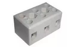
How to Wire SSR from Shining E&E?
Shining E&E SSRs are designed with four terminals. The top two are for the load (your device or equipment), and the bottom two are for the control signal (the switch power). Once you understand this, wiring becomes simple. First, we need to know what each terminal does:
-
Terminal 1 & 2 – Load side: Connect here the power and the device you want to control (for example, a motor or lamp).
-
Terminal 3 (+) – Control Positive: Connect to the positive side of the small control power (DC).
-
Terminal 4 (–) – Control Negative: Connect to the negative side (ground) of the control power.
Think of the control side as the “on/off button” and the load side as the “thing being turned on.”
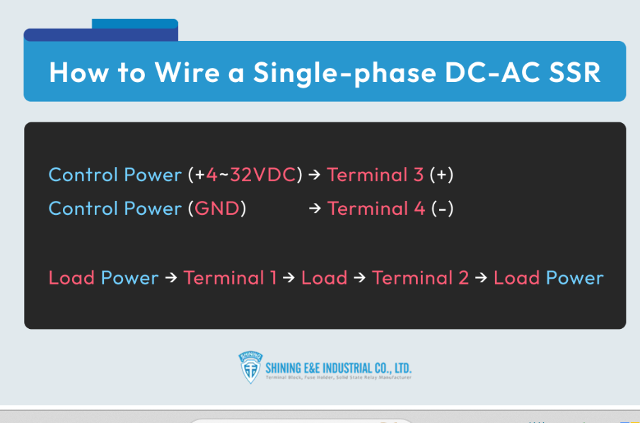
Wiring a Single-Phase DC–AC SSR
This type (model SSR-SXXDA) is often used when your control side is a small DC voltage, but your load is AC.
-
On the load side, connect your device (like a lamp or motor) between terminals 1 and 2. It works with 5–120 VDC.
-
On the control side, connect your DC signal (4–32 VDC). Terminal 3 gets the positive wire, and Terminal 4 gets the negative wire.
When the control signal is applied, the relay silently switches on your load.
Wiring a Single-Phase AC–AC SSR
If both your control and load are AC, then you’ll use the SSR-SXXAA.
-
On the load side, connect the AC device between terminals 1 and 2 (24–280 VAC).
-
On the control side, simply hook up your AC control voltage (80–240 VAC) to terminals 3 and 4.
That’s it—no moving parts, no clicks, just smooth switching.
Wiring a Three-Phase DC–AC SSR
Got bigger equipment, like a three-phase motor? That’s where the SSR-TXXDA comes in.
-
On the load side, connect each AC line (L1, L2, L3) through the relay outputs to your machine.
-
On the control side, it works the same way as the single-phase DC–AC version. Use a small DC signal (4–32 VDC) between terminals 3 and 4.
Single-Phase AC–AC SSR (Model: SSR-SXXAA)
-
Load side: Connect your AC load (24–280VAC) between terminals 1 and 2.
-
Control side: Apply 80–240 VAC to terminals 3 and 4.
This version is used when both the control and load are AC power.
Three-Phase DC–AC SSR (Model: SSR-TXXDA)
-
Load side: Connect each of the three AC lines (L1, L2, L3) to the relay outputs and then to your load.
-
Control side: Same as the single-phase DC–AC version. Use a 4–32 VDC control signal on terminals 3 and 4.
This lets you control a three-phase motor or other large equipment with just a small DC signal.
Shining E&E: Your Global Solid-state Relay Supplier
Solid-state relays bring together speed, reliability, and silent operation, making them essential in industries from medical equipment to industrial automation. By understanding how they work, their advantages, and how to select the right model, you can apply them with confidence in your own systems. But having the right supplier is just as important as choosing the right relay.
Shining E&E Industrial Co., Ltd. is here to support your projects with certified quality and over 40 years of expertise. Whether you need standard models or customized solutions, our team is ready to provide fast responses and competitive pricing. Contact us today or email us to request a quote or get detailed product information—let us help you power your business with dependable solutions.

| Solid State Relay | Electromechanical Relay | |
| Characteristics | Uses semiconductor devices | Uses electromechanical contacts |
| Size | Smaller size | Larger size |
| Speed | Almost instantaneous | Slower speed |
| Power Consumption | Consumes very little power | Requires more power |
| Noise | Generates very little noise | Can generate a fair amount of noise |
| Isolation | Better isolation due to no physical contact between input and output | Can provide isolation |
| Shock and Vibration | Not affected by shock and vibration | Affected by shock and vibration |
| Cost | More expensive due to manufacturing process | Less expensive |
| Lifespan | Longer lifespan with no physical contacts or arc generationr | Shorter lifespan due to constant opening and closing of contacts |
- industrial automation
- electronic appliances
- industrial appliances
- packaging machines
- tooling machines
- industrial lighting
- fire and security systems
- dispensing machines
- production equipment
- on-board power control
- test systems
- metrology equipment
- medical equipment
- display lighting
- elevator control